.png?width=300&height=157&name=spt%20logo%20png%20(1).png)
If a vial ever gets stuck in a pipe and must be recovered, you will need to use the low-level controls on the individual devices' pages. Do not attempt to do this if you have not been trained to do so, unless under the guidance of reliance engineers.
On many of the sub-system control panels are digital input and outputs. Use these to explicitly activate and deactivate outputs and to see the raw state of input sensors.

The image above is from the low-level Router control. It has two digital inputs; Air Supply OK and Vial Arrived. The input from the air supply pressure sensor is active and hence shown as blue. The Vial Arrived vacuum sensor is inactive and hence gray (the Vial Arrived vacuum sensor would only be high if suction was active and a vial was in the Router arm).
Below the digital inputs are two digital outputs: Blow and Suck. By clicking on the button beside these you can activate or deactivate each individual output.
All pneumatic valves in the system (in Senders, Receivers, Router, Buffer and Collection Points) can be manually controlled via the respective software control interface. You can also control the position of the Router arm, either by choosing a port number or by defining the motor step position for very fine control.
Once you have retrieved a stuck vial from a pipe, that pipe should not be used again until the cause of the transport failure has been determined. Disable the device at the end of the transport pipe by selecting the Take Offline menu option from the right-click menu for the device in the Overview screen while the investigation is undertaken.
NOTE: You can use instruments in Open Access walk-up mode while the lab2lab pipe is inoperable.
6.2.1 Overview
The default start-up view shows a schematic overview of your lab2lab system. This shows the Router, Buffer(s) and instruments as well as the relative positions of Senders and building2building Transceivers and optionally, their location within the building as you can drag and drop the lab2lab graphics to more accurately depict the layout of your system. Graphical elements show the overall system status as well as the status of all the main sub-systems.
On the right is the list of current vials. This is a simplified version of the main Vials table that can be seen in the Samples page.
- Click the Columns button to select which columns are shown in the Vials table.
- Click the Colour Key button to see the key for the color codes used in the Vials table.

During operation this page will show the movement of vials as the device LEDs change color to illustrate their status. In the above illustration, there is a vial in the Router and its barcode is shown. The vial list will also change as vial are registered, submitted and processed.
At the bottom of the window is a status bar. The right-hand side shows information about the current queue length, Buffer contents and number of vials and methods processed so far that day.
To view more detailed information about any of the key sub-systems either double-click on the graphic or use the menu bar. Sub-systems can be taken off-line (e.g. for routine maintenance) by right-clicking on them and selecting 'Take offline'. For instruments, the right-click menu has a second option allowing them to be taken off-line but some explanatory text must be entered which will then be displayed in the Client application so that users are kept informed about the system status.
6.2.2 Router
The main Router controller page shows the current position of the Router arm as indicated by a thick black line. This is only visible when the Router arm is stationary. During movement, no line is visible.
Use Settings on the Service page to disable Transport before using any of the Router controls. Taking direct control of the Router, or any sub-component of it, should only be done during
commissioning or error recovery.

To manually control the position of the Router, double click the desired position on the graphic or:
- Select the desired port (and destination, if applicable) from the dropdown list.
- Click the 'Move to Port' button.
The Router will then move the Router arm to the required position. The text at the top right shows the current port and the name of the device (if any) that it leads to, to confirm the move has completed.
To check if the Router arm contains a vial:
- Move it to the barcode reader position (port 0).
- Once it has moved, click 'Read barcode'.
Alternatively click the 'Check Catcher Contents' button which will automatically perform this complete operation. This will confirm whether there is a vial present and identify it.
The 'Home' button causes the arm to be re-homed. If the cover is removed the Router arm can be rotated, either intentionally or accidentally. Either way, the arm should be re-homed before the Transport function is re-enabled.
The Router-Motor-Bin-Barcode page has low level control for the Router: you do not need to access these during normal operation, but you may need to for error recovery.

Disable Transport on the Service page, then use the controls on this page to:
- Disable the Router.
- Check the Router bin vial count. You will need this as you cannot see into the Router bin to know how full it is. After you have removed a full bin and replaced it, click 'Reset vial count'.
- Use the barcode reader to read the barcode of e.g. a newly recovered vial.
- Move the Router to a port and then activate either the Blow or Suck valves, during error recovery.
The Air Supply OK input will remain high if there is sufficient air pressure in the Router’s air supply. The Vial Arrived input is only high when the Suck valve is open, and a vial is in the catcher block in the Router arm. The vial forms a seal on the air suction inlet which is detected. This means that when the Suck valve is closed this input will go low even though a vial is in the Router.
The Motor Control section can be used to move the Router arm to a specific stepper motor step count position. This level of control is typically only used by reliance during system setup, to get the precise motor positions for each Router port.
On the Router control are two areas labelled Network Comms and Digital I/O. The first of these indicates a network connection to the device. The second indicates that communication has been established for the control and feedback of sensors and actuators on the device. If these are not green, then there is a problem with communications over the network and you should contact reliance. If the “Log Comms” checkbox is selected then all the packet data to and from the device will be written to the log file.
6.2.3 Buffer
The Buffer page shows a graphical representation of the contents of the 96-cell rack in the Buffer; occupied locations, unidentified vials, empty locations etc.. If your lab2lab system has two or three buffers, there will be a separate page for each of them.

The table below shows all the possible symbols for rack cells and what they signify:
|
Cell Symbol |
Explanation |
|
Empty cell the cell is empty. |
|
|
|
Unidentified vial The cell contains an unidentified vial. When lab2lab has no higher priority activities it will transport this vial to the Router and read its barcode. |
|
|
Identified vial Cell contains a known vial. Hover the cursor over the cell and the vial’s barcode will be displayed in a tool tip. |
|
|
Cell currently under the Buffer’s transport pipe. A black border will appear on the cell currently underneath the Buffer port. This may be an empty cell, unidentified vial or identified vial. In the case of the latter two the appropriate vial image will appear in the middle of the square. |
|
|
Restricted cell During normal operation this will not appear. But by right-clicking on a cell the option to restrict a cell is available. This is typically only used by SPT Labtech staff during testing. |
|
|
Unknown cell status On retracting the Buffer stage, if the user informs lab2lab that the rack contents have changed, all cells in the rack (unless previously restricted) will be marked as Unknown. This means it is not known if they are empty or contain an as yet unidentified vial. |


You can right click on a cell to modify the contents e.g. to identify a vial or to set a rack location as empty. The options available will vary depending on the current contents of the cell.
Use the Eject button to eject and re-load a rack. On retracting the rack, you will be asked if the rack needs to be re-scanned i.e. have the contents changed at all. If the rack is to be re-scanned, then every position in the rack will be marked with the Unknown cell status symbol and inspected using the cap sensor under the Venturi block to see if a cap is present or not. If not, then the location will be marked as empty, but if a cap is detected then the status will change to Unidentified vial.
As the Buffer indexes through the rack, once you are certain that it has detected all the vials present, you can speed the process up by clicking on the 'Rack is Empty' button to inform the Buffer that there are no more vials to find.
6.2.3.I ConnectController
Director communicates with the ConnectController application which directly controls the Buffer.

The user interface for the ConnectController is very simple and shows the rack position as well as duplicating the cell status information from the Buffer page on the Director. In addition, it shows the sensor and output status for all 4 gates (only one of which will be connected to the lab2lab Router). The configuration of the Director will specify which of the four ports it is using. When controlled by the Director the text in the center at the top of the ConnectController will indicate that is being controlled externally by the system connected to port 1, for example.
If the Buffer is taken offline from the Director then, after 20 seconds, local control will become enabled and the text will say “Local Control” as shown above. In this mode the controls become enabled and through the ConnectController the rack can be moved to have any rack position to align with any of the 4 ports. The Lift valves and Gate actuators can also be controlled.
6.2.4 Instruments
There is a separate page for each instrument and its associated Receiver. This is an example page for a Waters instrument using the MassLynx interface: other instrument pages will have comparable controls, with slight differences e.g. there may be an additional output to indicate whether the autosampler's door is open.

In the case of an Agilent or Waters device a Vial Processing station consists of control software that handles communications with the instrument control applet and another applet to control the Receiver.
Use the controls on this page to:
- Check the status of the instrument and Receiver.
- Read the Router Port connection for the instrument.
- Manually control the Receiver to extend or retract the arm, test the cap sensor or the blow valve. You would usually do this in consultation with reliance.
- View the recent analytical history of the instrument (the most recent 40 analyses will be listed).
- View the available methods the instrument can support.
- Use the instrument Details window to view information about the connection e.g. the software version of the utility running on the instrument’s PC.
Below the Receiver control are two other status LEDs: Digital I/O and Network Comms. These are low-level systems associated with communications with the Receiver hardware. As with the Router, if they are not green (indicating that communications are ok) then the Receiver will not work.
6.2.5 Senders
There is a separate page for each Sender in the system. It displays its name, the number of the Router port to which it is connected and any descriptive text associated with it (as specified in the Director’s configuration file Config.xml). This could be the name of the room it is in or the floor it is on. The LCD control and LCD comms are for the use of reliance staff.

During normal operation it should not be necessary to access this page.
Use the controls on this page to:
- Check the Router Port and location description.
- Test the Sender LCD.
- Test the sensor inputs and digital outputs (the Blow output directly controls the Blow valve. The “Unsafe To Move” output is a logical output that relates to the indexing action of the Sender). You would usually do this in consultation with reliance staff.
As with other devices the Digital I/O and Network Comms sections indicate the state of the low-level communications. If these are not green, then the Sender will not operate.
6.2.6 Automation senders
There is a separate page for each Automation Sender in the system.
It displays its name, the number of the Router port to which it is connected and its current state (arm extended or not, vial present or not).
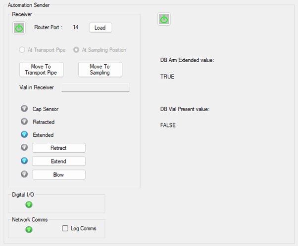
During normal operation it should not be necessary to access this page.
Use the controls on this page to:
- Check the status of the Automation Sender.
- Read the Router Port connection for the Automation Sender.
- Manually control the Automation Sender to extend or retract the arm, test the cap sensor or the blow valve. You would usually do this in consultation with reliance.
As with other devices the Digital I/O and Network Comms sections indicate the state of the low-level communications. If these are not green, then the Sender will not operate.
6.2.7 building2building
Each building2building transport system (if there is more than one installed) has its own page, with details of the installation. building2building operates automatically and unless there is a fault you should not need to access this page.
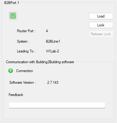
Use this page to:
- Check the connection between lab2lab and building2 building software.
- Shutdown building2building e.g. for maintenance, or to resolve a vial transportation problem.
- The Feedback text box will display any relevant message coming from the building2building control software.
6.2.8 Collection point
The Retrieval Bin (now named the Collection Point) page has the low-level controls for the Collection Point. It operates automatically and unless there is a fault, you should not need to access this page.

A Collection Point has a controlled gate and detects when a vial arrives. Shortly after a vial arrives on the gate Director will open it and drop the vial gently into the receptacle below. If the system was expecting the vial, then the Collection Point will inform Director that the vial has left the system. If the vial was not expected the gate will still open to drop the vial, but lab2lab will report that an unexpected vial had been processed.
Use the controls on this page to:
- Test the digital inputs and outputs.
- Check the Router Port connection number.
- Recover from a vial transport error by sending a vial to the Collection Point to remove it from the system.
Like the Router Bin, the Collection Point also keeps a count of how many vials it has received. There should normally never be more than one vial in the bin waiting to be collected or inspected if there was a barcode read failure.
As with other devices the Digital I/O and Network Comms sections indicate the state of the low-level communications. If these are not green, then the Collection Point will not operate.
6.2.9 Alarms
Optionally, lab2lab systems can include one or more alarms. These are small devices incorporating a light and a klaxon. Use the Director’s Config.xml file to set the alarm’s network ID and whether they are to use just the alarm or the alarm and the klaxon. If the Director’s config file is configured to include one or more Alarms, then an Alarms tab entry will appear in the Service page: ![]()
The controls for the Alarms connected to the system can then be accessed from the drop-down menu.

For each Alarm connected to lab2lab there is a separate control panel, as shown above. Use the controls on this page to:
- Test the light and klaxon outputs.
- Silence the alarm.
As with other devices the Digital I/O and Network Comms sections indicate the state of the low-level communications. If these are green, then communications are OK.
Lab2lab director: user interface - 6.3 Samples page >>>