.png?width=300&height=157&name=spt%20logo%20png%20(1).png)
Each Receiver is directly mounted to the autosampler of the host analyzer.
Services are connected to the rear of the Receiver. The Receiver ESD grounding is connected to an earth / chassis screw on the rear of the autosampler (so no additional provision is required post-installation).
You must ensure the PTFE pipe is able to drop vertically to the correct mounting position of the Receiver and inform SPT Labtech of its precise location for the installation.
4.5.1 Agilent instruments (Infinity II HPLC series, 1260 / 1290 Autosampler, GC8890)
lab2lab integrates with Agilent OpenLAB CDS. (version 2.7). This software application from Agilent can control both Infinity II instrument stacks and also specialist GC8890 instruments. To be integrated with lab2lab any Infinity II instrument stacks must use the Tube sampler version of either the 1260 or 1290 Autosampler (the 1260 and 1290 operate at different injection pressure but are identical as far as lab2lab is concerned).
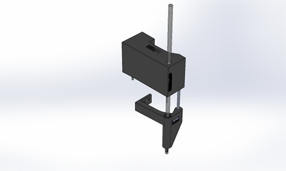
4.5.2 Agilent HPLC 1260 / 1290 receiver mounting
|
Part Number |
Description |
|
(2094-22000) |
lab2lab Agilent 1260 / 1290 Receiver |
- Separate the HPLC stack so that a metal saddle can be placed on top of the Autosampler.
- Replace the stack on top of the saddle.
- On the left side of the Autosampler are two locating pegs (at the remote tray location). Slide the Receiver into these.
- On the saddle are two thumb screws that the Receiver is screwed to. This supports the weight.

4.5.3 Agilent HPLC (1260/90 series) interface
This Receiver has a linear pneumatic shuttle that presents the vial at a location that equates to position 206 of the autosampler internal map. This position is used when an external tray is attached to the side of the autosampler.

4.5.4 Agilent GC receiver mounting
|
Part Number |
Description |
|
(2094-23000) |
lab2lab Agilent GC Receiver |
The Agilent GC Receiver is fitted directly over the 7650A Autosampler 'tower', as shown in the photo below.
4.5.5 Agilent GC interface
The Agilent GC Receiver contains a cap sensor and a blow valve. Unlike other Receivers, moving the vial to the instrument is done using the GC’s carousel. If the GC’s tower is attached in the front location then lab2lab tells OpenLAB to rotate the carousel from position 122. If the tower is in the rear position then carousel position 222 is used. The difference between the positions is solely an internal Agilent parameter, the GC Receiver is fitted onto the tower in exactly the same way.

When setting up the lab2lab GC integration be aware that:
- The carousel is not held in position when stationary; anyone can easily move it out of position.
- Agilent instrument control software provides no feedback to the lab2lab OpenLAB Controller as to the position of the carousel or whether it has been moved.
- the lab2lab OpenLAB Controller does not have direct control of the carousel, to issue a home command or drive it to a particular location.
These limitations affect how lab2lab can be used with GC8809s.
IMPORTANT: Ensure that anyone who is likely to come into contact with this lab2lab integration knows that they must not disturb the carousel and Receiver.
4.5.6 Setting up the lab2lab OpenLAB Controller (all listed Agilent instruments)
The lab2lab OpenLAB Controller utility needs to be installed on the PC that controls the instrument. The current version is 2.7.26, which is compatible with OpenLAB CDS 2.7. To use it:
- Set the correct PC name and TCP Port in the lab2lab Director Config.xml file. This is explained in detail in the 'lab2lab System's Administrator's Manual'.
- To permit scientists to register vials to be analyzed with the instrument, the names of valid analytical methods need to be added to the lab2lab Director’s (or Superconductor’s) method definition list in their local Lab2Lab.ini file:
[Agilent]Optionally, a processing method can be specified for each method, e.g.
MethodCount=4
Method.1=LOWPH-50
Method.2=LOWPH
Method.3=LOWPH-30
Method.4=HIPH
Method.3=LOWPH-30

Method.3.ProcessingMethod=C:\OpenLAB\ProcessingMethods\Method123.pmx
Note that the full, local path on the Agilent PC needs to be specified. This means that if there are multiple Agilent instruments on a lab2lab system that have the method called LOWPH-30 they must also have a local copy of the named processing method with the same path.
The Lab2Lab.ini file is explained in detail in the 'lab2lab System's Administrator's Manual'.3. Open the Agilent software, create a user account and grant them these “Roles” in the OpenLAB Control Panel:
Walkup Instrument Role

Instrument User

Instrument Administrator

Everything
4. Locate the Settings.ini file for the lab2lab OpenLAB Controller found in C:\ProgramData\SPTLabtech\Lab2Lab\OpenLABController. Director will communicate with the utility. This TCP Port number should match that found in the Director’s Config.xml file.
[Comms]Then, in the “Setup” section, add the name of the Agilent Project.
Port=16123
[Setup]When the lab2lab OpenLAB Controller utility first establishes a connection with OpenLAB CDS it will get feedback indicating the type of instrument being controlled, e.g. a GC or Infinity II stack. If the instrument is a GC8890, you can use Settings.ini to define whether the Tower Position is attached at the Back or Front coupling points. If the TowerPosition parameter is present the valid values are Back or Front (both case insensitive). If the parameter is missing or invalid then the default is Front.
Project=ProjectName
TowerPosition=Front
The username and password which you had set for the OpenLAB account need to then be set in the “Account” section of the Settings.ini file:
[Account]

Username=username

Password=password
5. When you are ready to start using the instrument and Receiver, start the Agilent software, then lab2lab OpenLAB Controller.

The status is shown as the utility initializes, as shown above. The two green ticks on the left indicate that the correct Agilent software applications are running.
- In OpenLAB, use the Release Control option on the top right menu. This enables lab2lab OpenLAB Controller to control the autosampler and instrument and 'Can Take Control' will show a green tick when this is so.
- Start lab2lab Director and bring the instrument online. Then the lab2lab Connection in lab2lab OpenLAB Controller will also show a green tick, indicating that the analytical instrument is ready for use with lab2lab. At this point the other fields will be populated.
4.5.6.I Initializing a GC8890
When OpenLAB CDS initializes a GC8890 the carousel goes through a homing sequence. The position that the carousel finishes at after doing an analysis is slightly different to where it is after homing. If you look at the lab2lab GC Receiver attached to the tower after homing, then you can observe that the drop pipe in the Receiver does not accurately line up with a hole in the carousel. Therefore, for lab2lab to work, the carousel must be aligned to the post-analysis finishing position. This means that when starting the system from shutdown the GC either needs to have a local method executed or for the carousel to be manually aligned for when the first lab2lab vial arrives. This issue does mean that any GC integrated with lab2lab needs to be in a controlled access environment where staff are aware of this issue and the need to reposition the carousel correctly after initializing.
4.5.7 Waters acuity classic receiver mounting
|
Part Number |
Description |
|
(2094-07000) |
lab2lab Waters Acquity Classic Receiver |
The Waters Acquity Classic Receiver mounts to the Waters Acquity Autosampler via 2 off M5x20 cap head screws (supplied).

- Remove fixing covers from the side of the autosampler, using a screwdriver.
- Remove the interior foam panel, to expose the mounting holes.
- Knock out the mounting holes visible in the molded side of the autosampler and discard the disks that have been removed.

- Remove the cover plate from the Receiver.
- Insert the 2 off top hat plastic bushes into the holes in the side of the Autosampler to locate the device.
- When the outside faces of the Receiver and HPLC are flush, insert the two M5x20 fixing bolts through the holes in the bushes and fix the Receiver to the autosampler, ensuring it is level.
4.5.8 Waters controller
The Waters Controller applet interfaces with the Waters Autolynx software, which in turn controls the Waters MassLynx software. The automation interface to Autolynx is quite basic and uses text files to indicate its status and to start a new method.
Interfacing to MassLynx controlling Waters instruments is achieved using the WatersController applet. The latest version of this is 2.7.26. SPT Labtech will assist with installation and configuration of this during commissioning.
Both the Classic and H/I/M class autosamplers are supported.
The WatersController has a plain text .ini file (located in C:\ProgramData\SPTLabtech\Lab2Lab\WatersController) and an XML config file (located in C:\Program Files\SPTLabtech\Lab2Lab\WatersController), both of which are read in at start-up.
4.5.8.I Waters controller .ini file
The typical contents of the ini file are shown below.
[Setup]
OLPDirectory=C:\MassLynx\OA\
RawOutputRootDirectory=C:\MassLynx\Open Access.PRO\Data\
QueueDirectory=C:\Autolynx\Queue\
ProcessedDirectory=C:\Autolynx\Processed\
FailedDirectory=C:\Autolynx\Failed\
TemplateOLBFile=C:\ProgramData\SPTLabtech\Lab2Lab\WatersController\Template.OLB
These are the various folder and file paths that the WatersController must know in order to operate correctly. They are generally self-explanatory, and all relate to the Waters MassLynx and Autolynx software, except for the path to the Template OLB file. This is a file which the WatersController copies, then renames and edits the copy, each time a method is run. An OLB file is what Autolynx reads-in to then control MassLynx. The WatersController Template OLB contains all the default parameters required as well as some with the value of “LAB2LAB_EDIT”. Parameters with this value are edited for each new method and the values are set to the appropriate value depending on what the user registered for their vial and also the content of the Director’s ini file.
4.5.8.II WatersController.exe config file
On start-up the WatersController also parses the contents of its config file. This is an XML file which mainly contains information used to set up logging. It should not require editing.
In the AppSettings section is the TCPPortnumber. This is a port that should be open through the firewall to allow communication with the lab2lab Director software. This value should tie-in with the corresponding entry in the Director’s config file parameter (see the 'lab2lab System Administrator's Manual' for details of the Config.xml file).
TCPPortNumber value="12348"
4.5.9 Waters acuity classic interface
For Waters Acquity Classic instruments, you will need to define a custom plate. When lab2lab presents a vial for analysis the position of it will equate to the first position in the rack.
- Within MassLynx click Shortcut -> Instrument -> Inlet Method
- Then click Acquity Sampler ->Rack generator
- Click New, and fill in the details as shown in the screenshot.

When commissioning the system it may be necessary to fine tune the X and Y Offset values for each Receiver/Instrument combination.
4.5.10 Waters H/I/M class receiver mounting
|
Part Number |
Description |
|
(2094-07003) |
lab2lab Waters H/I Class Receiver |
Tools required:
- 3mm Allen key
- X20 Torx driver
Step 1

Step 2

Step 3

Step 4

Step 5


4.5.11 Waters H/I/M class receiver interface
For Waters H/I/M Class instruments, you need to define two custom racks. One is for the position that a vial is presented by the Receiver. The second is for the QC positions in the lab2lab table insert.

Use the table insert if the instrument is being controlled by lab2lab. This will prevent the accidental placing of racks that could cause a collision. No tools are required to insert or remove this item.
- Within MassLynx click Shortcut -> Instrument -> Inlet Method
- Then click Acquity Sampler ->Rack generator
- Click New, and fill in the details as shown for the rack definition for vials presented by the Receiver.

- Create the rack definition for the QC sample in the lab2lab turntable insert.

When commissioning the system it may be necessary to fine tune the X and Y Offset values for each Receiver/Instrument combination.
4.5.12 Bruker NMR receiver mounting
|
Part Number |
Description |
|
(2094-14000) |
lab2lab NMR Receiver |
The Bruker NMR Receiver is affixed to a mounting plate.

- Fit the mounting plate and Receiver assembly onto the deck of the Bruker Sample Pro pipe liquid handler.
- Fit the Double-S acrylic pipe, ensuring it is in the correct orientation to not clash with the robot arm.
4.5.13 Bruker NMR interface
Bruker NMR integration with lab2lab is through Bruker’s Lab2NMR system. The lab2lab Director application communicates directly with the Bruker SamplePro Tube and SampleTrack software applications.
The Bruker software exposes two webservices; SampleProTube and SampleTrack. In the Director configuration file, the connection strings for these services need to be specified. The format for these is always the same, as is the TCP port used, so only the name of the Bruker PC needs to be edited.
Installing devices - 4.6 Sender >>>