Opening the Software
- Now samples are ready to scan!
- Double-click on the Scan icon
 on the desktop to start the Scan software.
 - Main processing screen is displayed (show below)
Scan Main Screen

- The default screen in the Scan software will be the main user screen after initial setup. This can also be found under the “Run>Scan” section of the sidebar.
- There are four main components to this screen:


- The main processing screen consists of a live image from the camera and a second tab, “Decoded Output”, that displays a list view of the rack ID and the individual decoded barcodes corresponding to their respective well position.
- Note: this list will be automatically updated when barcodes are decoded.

- The sidebar provides navigation through the various sections of the Scan software. These specific sections and their uses are outlined below.

- The action buttons in the top right corner should be all a typical user will require to decode sample barcodes. The three buttons are (from left to right):
- Camera On/Off
 or
or 
- Decode -

- Output File -

- Camera On/Off

- The status bar displays the status of the last decode on a given sample rack and will read the amount of passing decodes in a sample rack or cryobox. The currently selected “Rack Profile” will also be show in the status bar.
Reading and decoding a rack from the main screen
- After a rack or cryobox is placed on the unit and the software is open, the camera should display the image of the rack and corresponding 2D barcodes.
- If no image is visible, the camera may be turned off. The camera action button will have a red X next to the icon (shown below). In this case, simply click the camera on/off action button and a green ✓ should be next to the camera.

- Ensure the desired Rack Profile is selected by checking the name displayed on the status bar.
- If not, see “Rack Profiles” section below.
- Next, decode the 2D barcodes of the rack on the instrument by pressing the “Decode” action button. Green squares will appear around the 2D barcodes that have passed the decode (see image below) and the status bar will be updated to reflect the performance of the decode.
- This should decode quickly but can take a few seconds if the profile is not well tuned to the rack type or if there are advanced settings on.

- If the decode went as the end user expected, select the “Output” action button to output the file.

- Note: The file link can be clicked directly to automatically open the file in the default .csv application on the host PC
- The rack ID can be scanned automatically with the optional side rack barcode reader, by entering it in manually, or scanned using a handheld USB barcode reader into the prompt (enabled in Advanced Settings).

Profile Selection, Profile Editing and Profile Creation
- The Profile section of the sidebar is broken down into two sections.
- Select Profile
- Edit Profile
- Select Profile Window
- This screen allows users to Load, Save, and Save As Profiles.

-
- Load Profile brings up a dropdown list (see below) of the current profiles available to the user. There are a few defaults that come with the software to either be used for certain rack types or function as templates for custom profiles. Each profile in the dropdown list will have a Profile Summary shown on the right side of the page.


-
- Select a profile that reflects the rack or cryobox to be scanned on the instrument.
- Save Profile saves any settings changes to the currently selected profile.
- Save Profile As saves settings changes to a new profile name in an open text window at the bottom of the pop-up.

Note: The directory for profiles defaults to a SCANPROF folder. If you would like to change the directory, click “Change Profile Directory at the top left of the Save Rack Profile As or Load Profile pop-up windows and select a new folder for the directory.
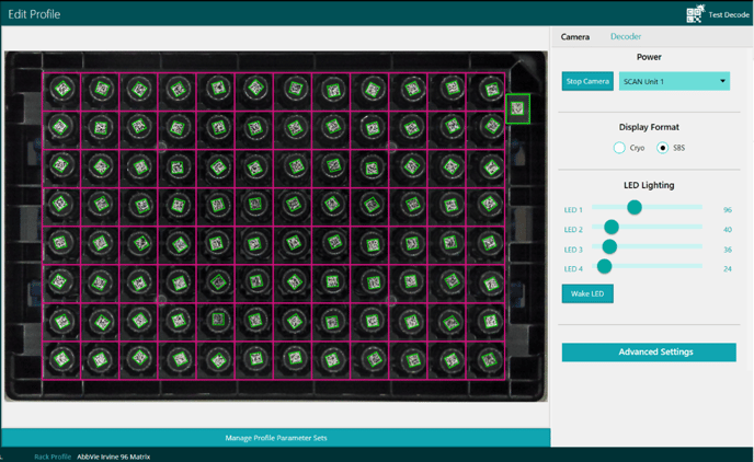
Edit Profile Screen
- The Edit Profile window (shown below) consists of a main viewing window with the live image from the camera, the toolbar on the right side, and a pop-up bar at the bottom.
- At any time during settings or template adjustment, the
 icon can be used to test the adjusted settings prior to saving changes. To test changes on the “Scan Main Screen”, the profile must be saved and confirmed it is loaded on the status bar.
- At any time during settings or template adjustment, the
- The toolbar consists of two tabs: Camera and Decoder
- The Decoder tab (shown below) allows the user to select the decoding grid of the profile by selecting the appropriate columns and rows of the sample labware.
- QuadCode Mode is also an option on the Decoder tab and is only applicable for quad coded tubes such as the acoustic tubes. This is default left off.

- The Camera tab allows the user to change multiple settings within a profile to optimize the image quality for seamless decoding. These are split up into three main sections: LED Lighting, Display Format, and Advanced Settings.

- The LED Lighting section contains four sliders that control the four LED light boards on the unit, one for each side. These do not need to be adjusted in most cases for SBS format racks but can be useful to optimize with cryoboxes as the barcodes will be closer to the edges of the instrument and catch light differently.
- The Display Format section provides the ability to switch between Cryo (see example below) or SBS formats by selecting the appropriate radio button.
- Note: This setting changes the zoom on the camera. SBS racks could be read in Cryo format, but ideal decoding would be in SBS format. Cryoboxes can only be read in Cryo format.

-
- The Advanced Settings section provides access to the Exposure, Gain, and Focus settings of the camera. These settings can be optimized for advanced or difficult use cases but should not be necessary for typical use.
- The main viewing area of the Edit Profile window (the live image from the camera) shows the view from the camera and the current grid size (in pink) selected in the Decoder tab. This area changes in real-time as settings are adjusted in the toolbar. There are three additional buttons available on this screen, below, and they can be accessed by right-clicking on the image.
- Normal View
- Zoom/Scale View
- Edit Template
- Edit Embedded Barcode
- Remove Embedded Barcode
- The Edit Template option allows the user to condense, stretch, or drag the grid to best fit the image of the rack on the scanner. The grid should be positioned so that there is one 2D data matrix barcode position per square and the barcode fits with some space from the pink gridlines. See below.


- The other option that can be used in this screen is the Zoom/Scale View selection (shown below). This allows the user to zoom in on a particular area of the image to get a better look at a particular barcode or section. This can be useful to see how the settings selected perform in different areas of the image (e.g., lighting).


-
- The size of the Zoom/Scale View area of view can be expanded or contracted using the scroll wheel on your mouse.
- Lastly, this view enables the use of the auto-focus feature. If the user would like to change the area of focus for the image, simply hovering over the target area and left-clicking with the mouse will automatically change the focus of the camera to the target.
- The final options on right-click menu are Edit Embedded Barcode and Remove Embedded Barcode. This applies to racks with an embedded rack 2D barcode on the bottom or commonly called the “97th barcode.”

-
- The Edit Embedded Barcode option creates a resizable green rectangle that can be moved to the location of the 2D rack barcode. If saved to the profile and enabled in settings, this location will be scanned for a 2D rack barcode with each rack scan.
- The Remove Embedded Barcode option removes the green rectangle for the embedded barcode from the current profile when saved.
- Note: Example of how embedded barcode appears in the output table view.

Saving Changes
- Profile settings changes can be saved in a few ways.
- After creating a new profile or editing off a template, Save Profile As allows the user to name the new profile whatever they like.
- This can be achieved by going to the Select Profile section of the sidebar and selecting the Save Profile As button or by going to File>Save Rack Profile As (shown below). Either selection will prompt the user to name the new profile.

-
- The other option is: Save Profile which simply saves over the currently loaded profile. For more complex profiles, see the next section on “Managing Profile Parameter Sets.”
Managing Profile Parameter Sets
- The Manage Profile Parameter Sets pop-up bar gives more flexibility to the user. Parameter sets concatenate settings changes to the currently selected profile. This is a useful tool for difficult labware or advanced operations as the camera settings can go through iterative adjustments within one profile to decode racks.

- There are five action buttons for managing parameter sets, Insert, Append, left arrow, right arrow, and the trash can icon.
- If edits are made to a selected parameter set, they can be saved over current values, but if the end user would like to iterate over multiple parameters, a new set can be added by clicking on Insert or Append.
- Insert – adds a new parameter set tile to the bar using the current selected settings from the Camera settings toolbar. Insert adds this new parameter tile before the currently selected parameter tile.
- Append - adds a new parameter set tile to the bar using the current selected settings from the Camera settings toolbar. Append adds this new parameter at the end of the sequence.
- The left and right arrow buttons - move the order of the currently selected parameter tile. The left arrow moves the tile up in order and the right arrow moves the tile down in order.
- The trash can icon – deletes the currently selected parameter tile from the set.
- If edits are made to a selected parameter set, they can be saved over current values, but if the end user would like to iterate over multiple parameters, a new set can be added by clicking on Insert or Append.
- All changes will need to be saved to update the profile with parameter set edits, additions, and deletions.